


Learn about jigs on lathes
Đăng bởi noidung - 10:22 14/05/2022
Learn about the types of jigs on lathes
The jig, also known as the chuck on the lathe, is a technological device that plays an extremely important role in the process of machining, testing and assembling products.
Machining jigs on lathes are extremely diverse. For example: jig on chuck, jig on center points… Here, we invite you to learn about some typical machining jigs on lathes with Cosmo .
Fixtures on lathes are composed of 2 parts: mandrel and workpiece. Below is a detailed article about each type.
Cylindrical rigid mandrel
– Cylindrical rigid mandrel: machined with Ø350 diameter of impeller.
Workpieces: are positioned on the mandrel and use nuts to clamp.
Both the mandrel and the work piece are mounted on two center points. In the case of torque transmission, speed pairs are used.
Elastic mandrel
– Elastic mandrel: has the effect of positioning and helping to clamp the details.
– Workpiece: used to position on the elastic mandrel (according to the inner cylinder face) and the face of the mandrel body.
Thus, if you want to clamp the part, you must tighten the nut. When tightening the nut, you also need to pay attention to the taper detail moving to the left, this will cause the elastic mandrel to expand, making it easier to clamp the part. The mandrel body (conical) will be mounted on the main shaft of the lathe. The clamp will then be retracted from the rear of the spindle.
Elastic collet
– Elastic collet: used to position and clamp the work piece along the outer cylindrical surface.
– Workpiece: is positioned inside the elastic collet according to the outer cylindrical face and is pressed against the end face of the part.
Thus, in order to clamp the details tightly, the nut must be tightened. While tightening this nut, you should move it to the left, which will cause the elastic collet to be squeezed and clamp the part.
Mandrel with disc spring
– In contrast to the elastic collet that positions and clamps the part along the outer cylinder, the mandrel with disc spring is used to position and clamp the part according to the inner cylinder.
– Mandrel consists of 5 parts: body, stop ring, disc spring, collet and screw. When tightening the screw, the collet will deform the disc springs in the radial direction to help clamp the part. The body part will be installed in the taper hole of the main shaft and clamped by a drawbar at the rear of the main shaft.
Self-tightening mandrel with a roller
– Mandrel is structured together by only one roller, including 5 parts: roller, spacer, set screw, locating pin and mandrel body.
– And the roller must be ground until the diameter D and the diameter of the mandrel body are equal. The workpiece is clamped tightly thanks to the centrifugal force of cutting.
Self-tightening mandrel with three rollers
– The mandrel clamps itself together with three rollers arranged 1200 apart, each with a spacer between them.
– Before mounting the work piece, these spacers must be turned to an angle and allow the rollers to be in the lowest position. And this separator will automatically return after the work piece is fixed, and the roller is pre-tightened. The work piece is pressed against the left edge of the mandrel when the nut is tightened and is pushed by the balls and washers.
Head and hole turning jigs
For face and hole lathes, the work piece is positioned on the round seat and the cylindrical part of the mandrel.
Thus, the clamping of the part will be done with two clamps. The taper end of the mandrel will be inserted into the taper hole of the main shaft and clamped by a drawbar at the rear of the main shaft.
Hole turning jigs at the top
– A special feature of the hole turning jig on the head face is that the center of the hole will be machined so that it does not coincide with the center of the main locating hole.
– The part to be processed will be positioned on the round slab. The pivot pin and anti-rotation support pin will help clamp the part with two clamps. Since the center of rotation of the work piece does not coincide with the center of the centering hole, we will have to mount the object part. This is to help create balance when machining.
Concave deck turning jigs
The concave deck turning jig with the work piece is mounted on the lathe’s 3-spoke chuck.
The body of the fixture will be installed in the dynamic dock of the machine. The gear engages with rack 1 and the tail 5 of the rack with the tool holder will be mounted on base 6.
When the tool holder, base and end of the rack move backward (perpendicular to the spindle center), rack 1 causes gear 2 to rotate clockwise along with tool 4 to produce a sphere of radius preselect.
Chuck
The chuck is used to clamp and fix the parts when machining, the chuck is mounted on the main shaft through the locating tapered surface and the thread on the spindle head.
There are two types of chucks: self-centering and non-self-centering.
Self-centering chuck is a chuck used to clamp round workpieces, when clamping workpieces whose center coincides with the center of the spindle, there are two types of self-centering chucks: pins, 3 prongs, 4 prongs and 6 prongs and often in machining people use a self-centering 3-spoke chuck.
Non-self-centering chuck (Chuck with independent jaws): is a chuck with radial displacement spokes independent of each other in the rims of the chuck, where each jaw has half a nut that engages with the screw. me , one end of the lead screw has a square hole to insert the wrench , when the lead screw is turned , the corresponding chuck will move radially , The chuck is not self-centering usually to clamp asymmetrical parts or clamp to machining eccentric parts.
Bài viết liên quan

Yamaha to showcase automated transport, production solutions at 2023 International Robot Exhibition
04/11/2023
Xem thêm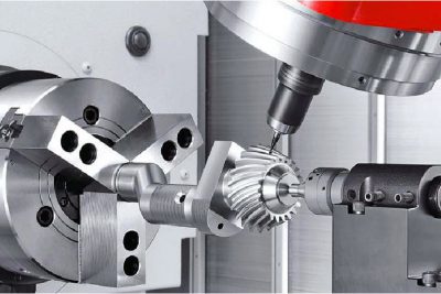
Learn about on-demand mechanical processing
25/05/2022
Xem thêm
Things to pay attention to when using a mechanical tool
25/05/2022
Xem thêm
Mechanical Materials, Introduction to Mechanical Materials
25/05/2022
Xem thêm
Price list of industrial conveyor systems
25/05/2022
Xem thêm
Comments